

DAZLE – the design
Introduction
DAZLE, the Dark Ages 'Z' Lyman Explorer, was funded from the PPARC
Opportunity Scheme, which was set up to encourage truly innovative research,
demonstrating originality and creativity. DAZLE is being built here at the
Institute of Astronomy, University of Cambridge, UK. We collaborated with our
colleagues at the Anglo-Australian Observatory, Sydney, Australia for a large
part of the mechanical design.
DAZLE is intended to be the first imaging instrument optimised to
detect faint emission lines between the intense lines of the OH airglow
spectrum that hinders current ground-based observations. In conjunction with
the improved image quality now demonstrated with new 6.5-10 m telescopes, DAZLE
will be the only instrument well suited to searching for early star-forming
systems located beyond the redshift range probed by current instruments for at
least the next 5 years. The predicted flux limit for detecting un-reddened
Lyman-alpha emission at redshifts of 10 corresponds to a star formation rate of
only 1 solar mass per year. The large format detector we have available in the
CIRPASS camera makes it ideal for wide field survey work.
Functional Concept
The fundamental idea of DAZLE is to use the camera from CIRPASS in
conjunction with very carefully chosen and constructed narrowband filters to
detect high-z galaxies by differential imaging of redshifted Lyman-alpha
emission at a specific wavelength, selected to be free of atmospheric emission.
The CIRPASS camera has particularly low noise, high sensitivity and good
imaging characteristics that make it especially suitable for this application.
DAZLE is intended to operate as a VLT visitor instrument, on the
Nasmyth platform of VLT UT3. Such a concept immediately requires certain system
components:
- The VLT Nasmyth focal plane needs to be collimated for input to
the CIRPASS camera.
- Extremely specialised and carefully specified filters are used
for differential imaging. The technology to construct filters suitable for the
purposes of DAZLE has only relatively recently been demonstrated.
- A filter exchange mechanism is required to swap the filters for
differential imaging.
Further constraints on the system are imposed by operational and
design features of the CIRPASS camera, and constraints imposed by ESO on
visitor instruments fitted to the VLT. The CIRPASS camera is designed to
operate viewing vertically downwards, and so cannot be mounted directly on the
VLT Nasmyth rotator to track the rotating sky image during exposures. This
means that a fold mirror must be used to turn the horizontal axis of the
Nasmyth focus vertically so it may be imaged into the camera, and the camera
rotated to track the sky by a mechanism that duplicates the action of the VLT
Nasmyth rotator, but with a vertical axis. ESO impose additional constraints on
visitor instruments at the VLT:
- Size and weight
- Vibration transmitted to the VLT structure
- Heat transfer to or from the telescope enclosure
- Earthquake survivability
- Health and safety requirements
The CIRPASS cryogenic camera is operated at approximately –190°C,
being cooled by liquid nitrogen.
A sensitivity analysis further revealed that to achieve the
required performance the complete DAZLE optical train needs to be maintained at
a low temperature (-40°C), and so a refrigerated enclosure is needed to house
the complete system on the Nasmyth platform.
Design
The mechanical assembly is shown in Figure 1 below. In this
design, the DAZLE instrument is housed in a refrigerated enclosure raised to
the height of the Nasmyth focus on a sub-frame.
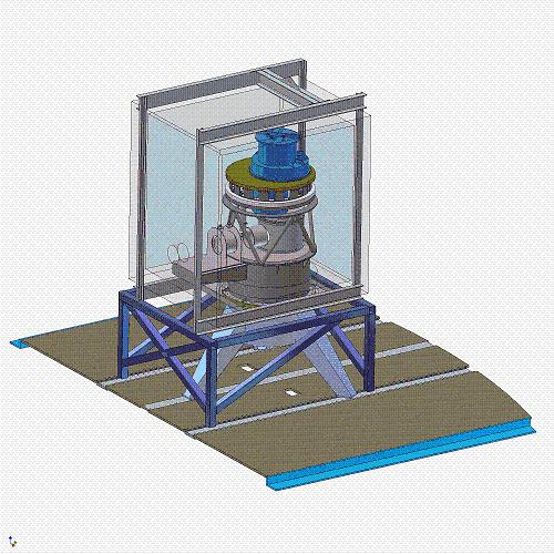
Figure 1: DAZLE, mounted on the VLT UT3 Nasmyth platform
A collimator aligned with the Nasmyth focus collimates the input
(f/15) beam and directs it to a fold mirror beneath the CIRPASS camera. The
CIRPASS camera is supported in a structure that provides rotation capability
for tracking the sky image. A filter deployment mechanism is mounted
immediately beneath the camera, using filter wheels to swap between the
narrowband filters for differential imaging. The overall assembly is described
in the following substructures:
- Support structure
- Camera assembly
- The optical train
- Filter and mask wheel assembly
- Insulating enclosure
Support Structure
The support structure
consists of a tripod to raise the complete instrument to the height of the
Nasmyth optical axis, and a ‘saucepan’ to support the optical components of the
collimator, the fold mirror, filter and mask wheels assembly, and the CIRPASS camera.
The tripod is on the ‘warm’ side of the instrument at ambient temperature,
while the saucepan is maintained at –40oC within the refrigerated
enclosure. A thermal break is situated between the two.
Camera rotator assembly
The assembly in Figure 2 shows the components of DAZLE that
support the CIRPASS camera, enabling rotation to track the sky during an
exposure. Such rotation is an exacting requirement, and the bearing selected to
enable this needs to be exceedingly accurate. The AAO selected a suitable
bearing (originally intended for use with a radar tracker!) and conducted tests
to verify that the axial runout specification is met by this precision bearing.
At the IoA we have carried out
stability tests of the complete rotator system, to verify that it meets our
specification.The complete rotator and camera assembly is supported above the
saucepan by an open tube system providing the necessary degree of stiffness.
The camera is rotated via a high resolution control system driving a stepper
motor and a 100:1 gearbox, enabling it to track celestial objects.
Figure 2: The camera rotator assembly
The optical train
A five-element chromatic design of standard Schott glass, arranged
in two groups, is used to collimate the light from the VLT Nasmyth focus. As
the filter band-pass is extremely narrow – about 1 nanometer – an achromatic
design is unnecessary. All lens surfaces are spherical. The first two elements
act as a double-glazed window to the refrigerated enclosure. The last three
elements move together to enable the collimator to be focused.
The collimated beam is turned through 90 degrees by a fold mirror
to direct the beam towards the filter and mask wheels assembly and the downward
facing camera.
Figure 3: The DAZLE
optical train
The heart of the instrument is the pair of narrow band filters in
the collimated space. These two filters are separated by a few nanometers in
wavelength, with their central wavelengths chosen to fit in gaps between the
strong night sky OH emission. Imaging is essentially carried out in a
differential mode – images are taken through the two filters, and one image
subtracted from the other. Any object still seen in the subtracted image is a
potential Lyman alpha emission.
The light beam then enters the cryogenic camera borrowed from
CIRPASS. Again, this is a five element chromatic design, using standard Schott
glasses, and with all spherical surfaces. The detector is a state of the art
Rockwell Hawaii II, 2048x2048 Mercury-Cadmium-Tellurium device. Fine focusing
of the camera is achieved by moving the detector assembly using cryogenic
stepper motors. The camera incorporates several long pass filters to stop the
detector seeing any thermal emission.
Filter and mask assembly
The wheels assembly contains two wheels, one containing the pair
of narrow band filters, the other containing masks used when focusing DAZLE. It
is mounted in the collimated beam in between the fold mirror and the camera. A
pupil image is formed close to the upper surface of the wheels assembly, and so
the system incorporates a cold stop, preventing the camera from seeing the warm
exterior outside the cold room.
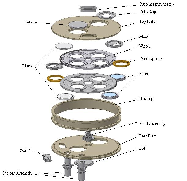
Figure 4: Wheels assembly
Insulating Enclosure
The instrument is enclosed within an insulated cold room,
maintained at a system temperature of -40°C. The cold room is supported by its
own support framework and is detached from the instrument itself. Thermal seals
bridge the gap between the cold room and the instrument support. Cooling is
provided by an external refrigerator, and an evaporator inside the cold room.
Electrical, vacuum and liquid nitrogen supplies are fed through interface panels
in the enclosure walls. Our experience with CIRPASS has shown this type of cold
room is perfectly adequate to maintain the internal temperature at up to 65°C
below ambient.