Structure in reset frames
11 Jan 2000
rgm/aef took data at Las Campanas on 15 Dec 1999 with reset subtraction
in Pixcel turned off (run 9137, 4 loops). The output images (one per
quadrant per chip) are 1024x512, with the reset image for that quadrant on
the left and the data on the right. These reset images were extracted and
assembled to form a reset image (1024x1024) for each loop.
Run 9137:
Raw data with no on the fly processing
One 1024x512 image per chip quadrant containing reset and data portions
RRR mode
assemble off
rotate off
subtract off
read 000 contains the reset for read 001
read 001 contains the reset for read 002
etc.
The original data, the assembled reset images (1024x1024), the difference
images (loop 1 - loop 0, loop 2 - loop 1, etc), and the average of
the difference images are in /data/cass60d/sabbey/reset along with all
the IDL programs used.
Result:
The reset images have a signal level of about 4000 counts and structure
on large and small scales (including an odd/even stripe effect) at the
level of a couple hundred counts. If the structure is constant then
it will be eliminated from the data by the reset subtraction done by
Pixcel.
However, at loop 1 (reset frame loop 1 - loop 0), there is significant
residual reset structure. Most noticeable is a ramp of amplitude about
100 counts that appears as a dark band along the edge of each quadrant.
Also, there is an odd/even stripe effect of signal level about 50 counts
that is parallel to the dark band. Additional structure in the other
direction has an amplitude of about 20 counts. By loop 2, the residual
reset structure has greatly diminished, and is no longer apparent by
loop 3.
Possible solutions:
1) Take many loops and discard the first one. However, if many
loops are taken then the time between dithers is longer which is
undesirable for IR data. If the exposure time is reduced then
observing efficiency decreases due to read-out time.
2) Modify Pixcel to do continuous read-out. The observing sequence
is controlled by CSequenceTask::PerformTask() in gci2/seqtask.cpp of
the Pixcel software. At the end of an observation, PerformTask()
puts the camera into Idle mode (line 443). Idle() mode is defined
starting at line 330 in cgui/observedlg.cpp. Idle() first calls:
pCamera->PreFlushes(pParams->m_NoOfFlushes.Setting());
which appears to turn on preflushing. Idle() then calls:
pCamera->PerformAction(FlushAction);
which has no effect (the switch statement in PerformAction() only has
a comment for FlushAction, line 244 in gci2/capellac.cpp). Then:
pCamera->PerformAction (TakeAllAction);
which would call TakePicture() at line 217 of gci2/capellac.cpp but
that has been commented out. Idle mode needs to be modified to take
data and not save it.
3) Apply reset correction in the data reduction. Assume that observations
from all loops at a given run are first averaged (the data reduction
is easier that way). The average reset frame residuals (the
average of loop1-loop0, loop2-loop1, and loop3-loop2) have a ramp
amplitude of about 30 counts, odd/even stripes of amplitude roughly
20 counts, and additional structure at the level of 20 counts. If
we subtract the row median from each row we obtain a good first
order correction to the reset frame residuals. The remaining structure
is at the level of ~< 10 counts. In practice, the mode would be
used instead of median, and object pixels should be masked first.
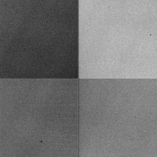
The reset frame (loop 0) assembled from the separate quadrant images
written by PixCel with subtraction turned off. The signal level is
about 4000 counts with structure with an amplitude of a couple hundred
counts.
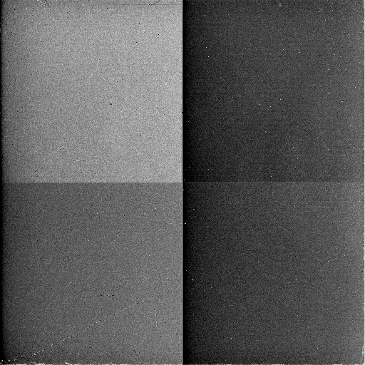
The difference of assembled reset frame loop 1 - loop 0.  The most obvious
structure is the reset ramp (the dark band along the edge of each quadrant).
The ramp and other reset residual structure will appear in loop 1 data
frames.  The ramp and other structure are greatly diminished in loop 2
data and no significant reset residual structure is expected in loop 3
and later loops.
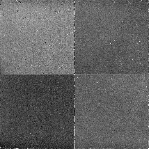
A first order correction to fix the reset ramp is to subtract the median
of each column from each column.  Here is the corrected version of the
above loop 1 - loop 0 reset frame:
Analysis of quadrant 1 of loop 1 reset - loop 0 reset frames.  In addition
to the reset ramp, the odd/even stripe effect and other structure is seen.
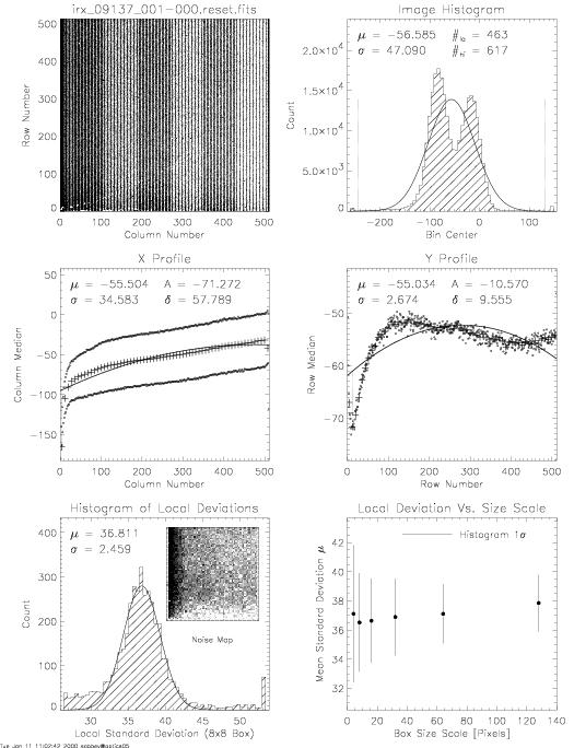
The reset level stabilizes with time and minimal reset structure if any
is expected in later loops. Below is the analysis of quadrant 1
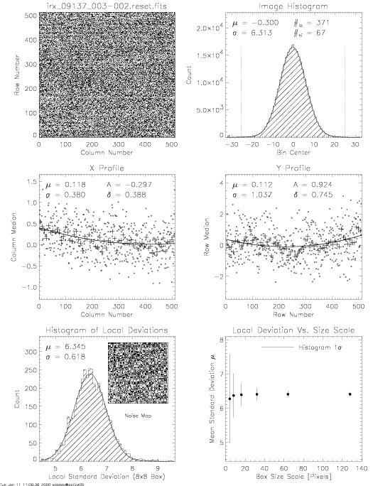
of loop 3 reset - loop 2 reset.
Contact: sabbey@ast.cam.ac.uk
Last update: Tue Jan 11 16:08:07 GMT 2000